A nice use for the Attiny85 — a canon DSLR infrared remote.
Parts required
- Attiny85 microcontroller
- NPN transistor
- 3.3 or 5 V voltage regulator
- Pushbutton
- Infrared led
- 12v car key/alarm battery
- Some copper clad board
Design the PCB
Tweak the design for better looks in Illustrator (Download printable PDF)
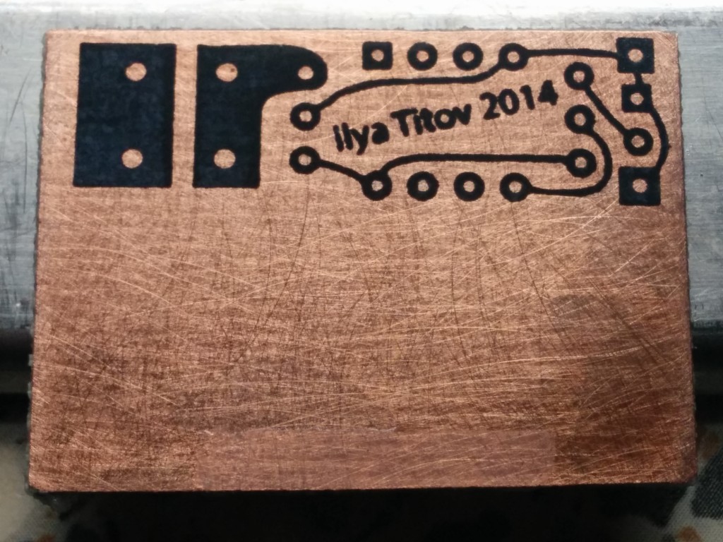
Print and transfer the pcb design to the board (laser printer/laminator method)
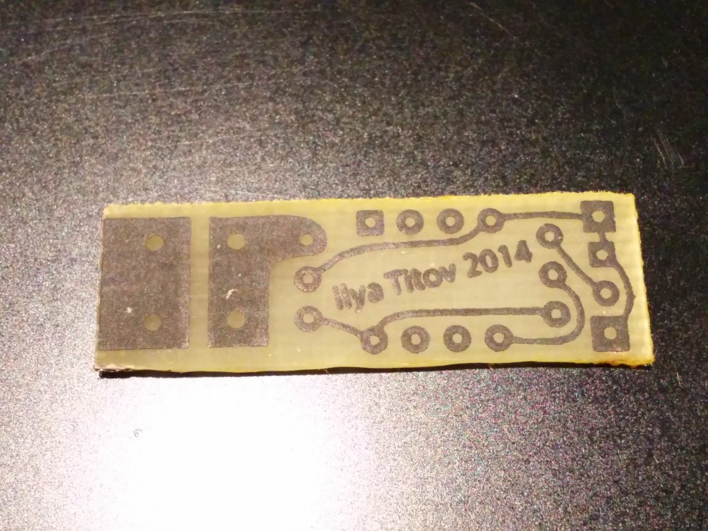
Trim the board with a dremel and etch with ferric chloride and some 3D printer assistance
Gcode for rocking the print bed
G21 ; set units to millimeters
M107
M92 X62.6054 ; calibrate X
M92 Y61.0152 ; calibrate Y
M92 Z2387.0719 ; calibrate Z
G90 ; use absolute coordinates
G1 Y100
G1 Y110
G1 Y100
G1 Y110
G1 Y100
G1 Y110
G1 Y100
G1 Y110
.... just copy-pase the last 2 lines to extend print time
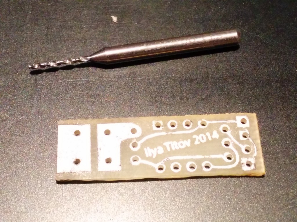
Wipe off the toner with acetone, tin and drill the holes using .8mm carbide drill
Solder the parts and add battery contacts made from a paperclip
Program the attiny85 with the following code (16 15us pulses, pause for 7330us and do 16 15us pulses again)
I am ussing the assembler port calls to trigger the pins because digitalWrite() function is too slow
void setup() {
pinMode(0, OUTPUT);
}

void loop() {
int del = 15;
int del2 = 7330;
for (int i =0; i<16; i++){
PORTB |= _BV(PORTB0);
delayMicroseconds(del);
PORTB &= ~_BV(PORTB0);
delayMicroseconds(del);
}
delayMicroseconds(del2);
for (int i =0; i<16; i++){
PORTB |= _BV(PORTB0);
delayMicroseconds(del);
PORTB &= ~_BV(PORTB0);
delayMicroseconds(del);
}
delay(100);
}
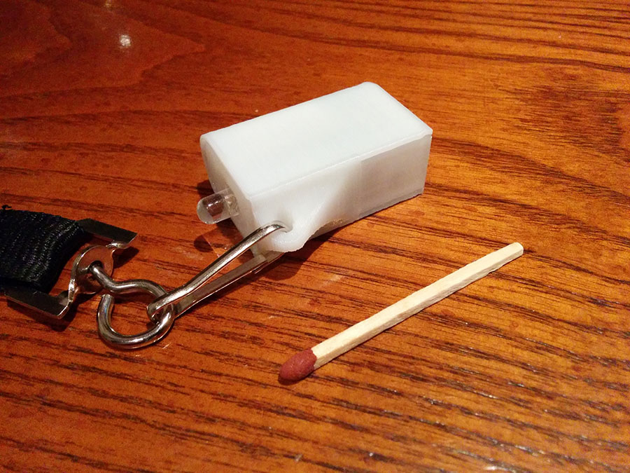
Model and 3D print the keychain case (Download printable file from Thingiverse)
References
Programming the Attiny85 http://highlowtech.org/?p=1706
Timing for the trigger signal http://www.doc-diy.net/photo/rc-1_hacked/index.php


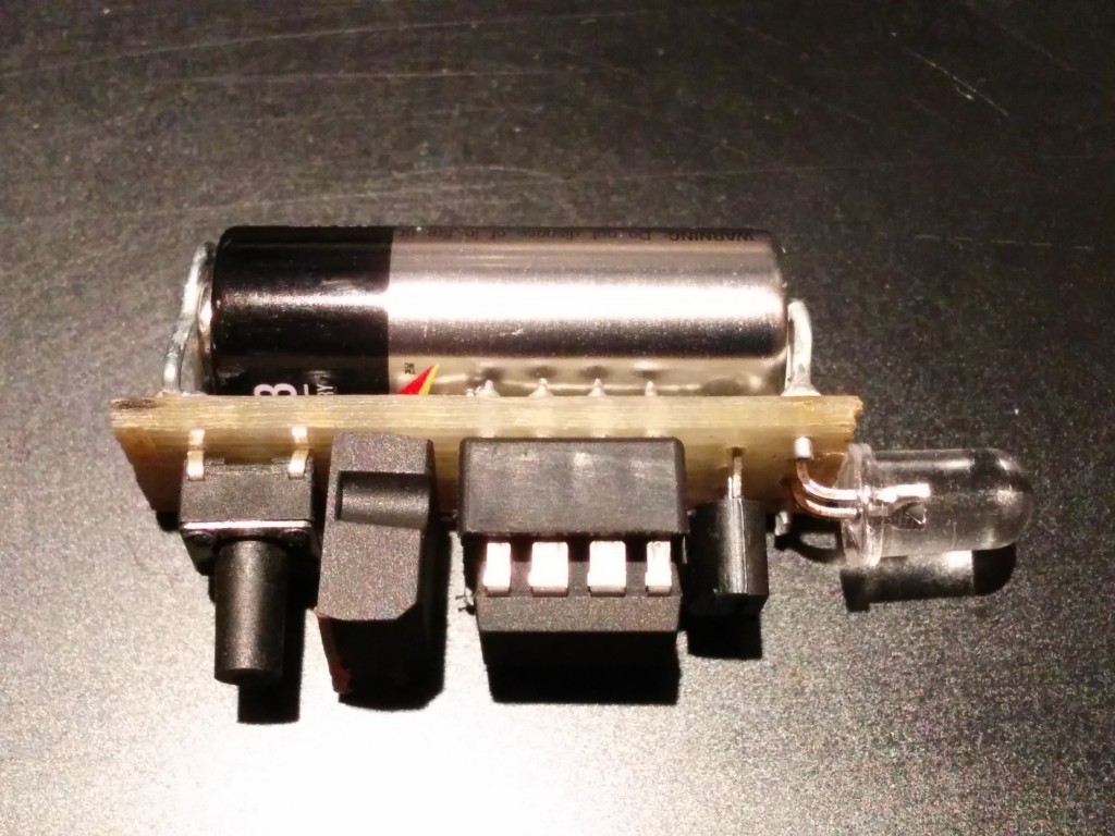

What is it between the switch and the ATtiny85 please
Dip8 socket?