 All the latest code and pcb files are available on github, go make!
![]()
If you want to get in touch about the kit please tweet @webboggles, otherwise you might find that it takes me a long time to reply to comments here.
Games
You aren’t going to run DOOM on an 8K chip but its still capable enough to run some classics! See the Github repos, there are a few games there.
New Board!
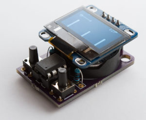
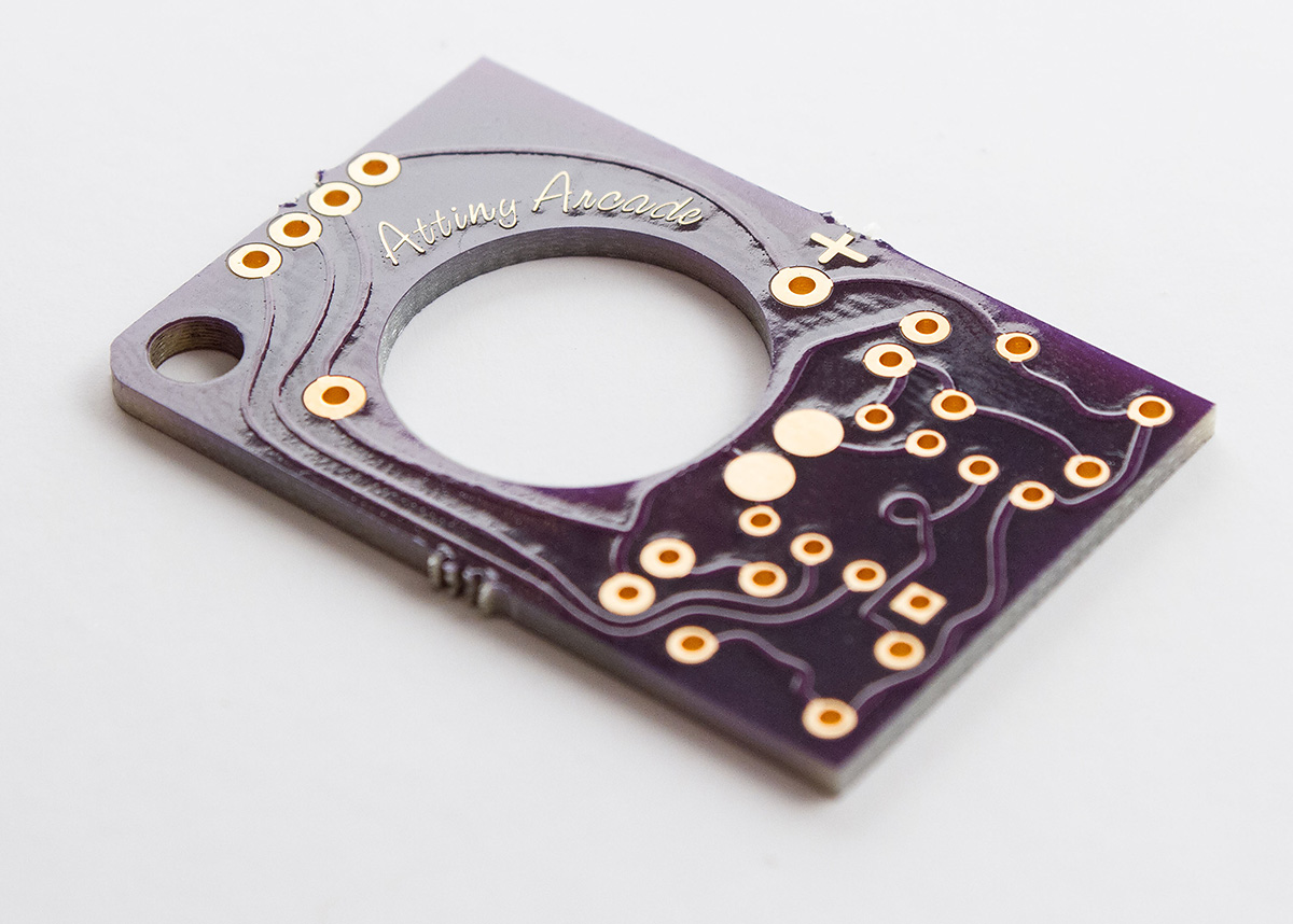
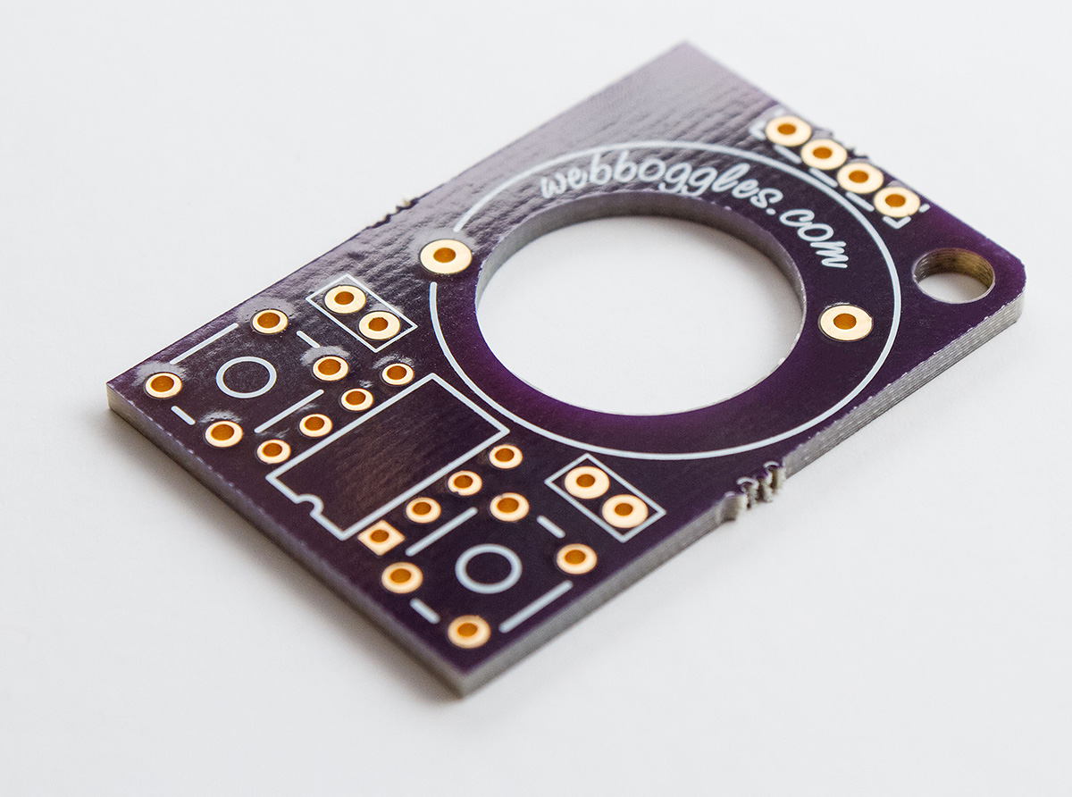
I am using OSH Park to manufacture the PCBs and they are doing a great job! Purple solder mask and immersion gold finish, don’t they look good?
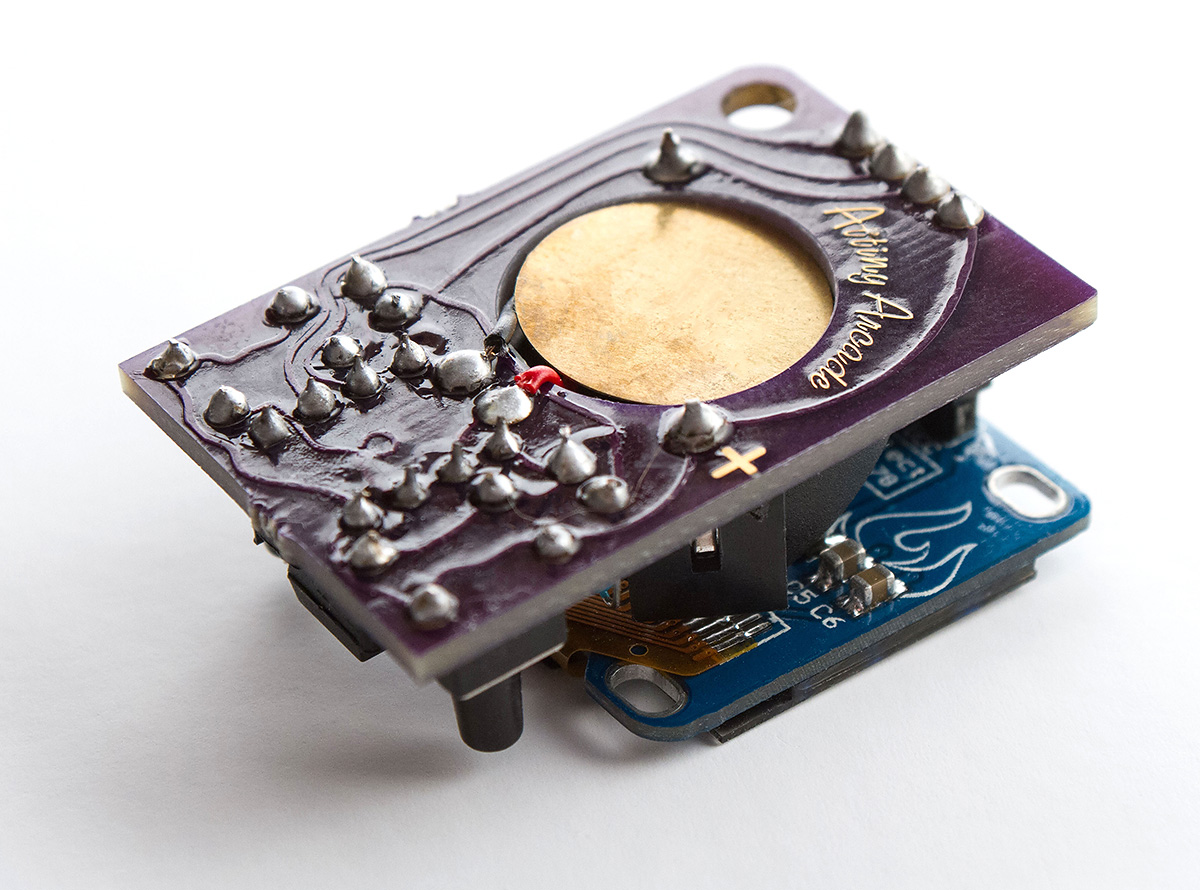
You will also notice that I cut a hole to fit the 15mm piezo element flush with the board. This makes it so much neater.
Dev repos
Ilya’s git repo: https://github.com/webboggles/AttinyArcade
Andy’s git repo: https://github.com/andyhighnumber/Attiny-Arduino-Games
Other resourses
Assembly step by step .pdf
UFO Escape.ino
Oroboros.ino
Breakout.ino
Canond DSLR Remote.ino (add 940nm IR LED to piezo pads)
PCB printable .pdf Please note the sck and scl pins in this older design are swapped around, you will need to amend these in the sketch if the screen doesn’t turn on.
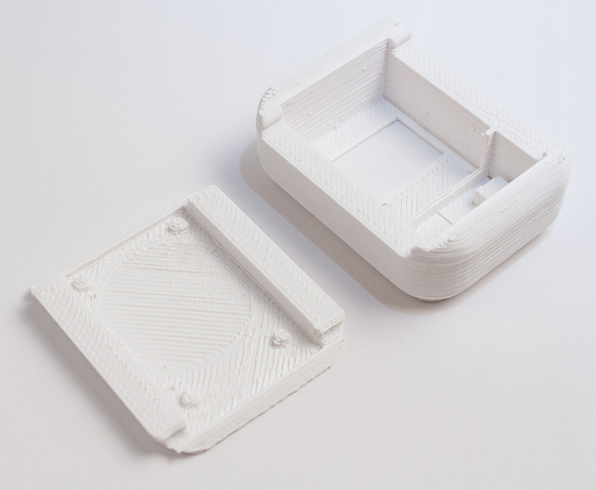
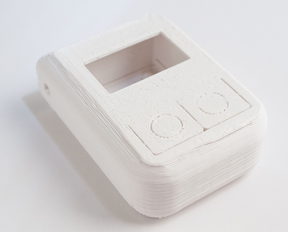
3D printable snap case .stl files or on Thingiverse
SSD1306 library courtesy of Tinusaur
Everything above in one Google Drive folder
Update 2017/01/13: Andy Jackson refactored game code to fit two games in one cketch (https://drive.google.com/drive/u/0/folders/0BxGfuaPdM4n0bjVDSjc0WEFJVTQ)
Update 2017/01/22: Awesome “Space Attack” game by Andy Jackson:
https://drive.google.com/drive/folders/0BxGfuaPdM4n0Z1ZfNnAxZHFvams?usp=sharing
Update 2017/02/26: Andy’s repo (Wren Rollercoaster, Space Attack, UFO Stacker, Bat Bonanza) https://drive.google.com/drive/folders/0BxGfuaPdM4n0Nkt5TDI4azd1Rmc
Update 2021/01/03: John Bradnam ported some games to ATtiny1614 https://www.hackster.io/john-bradnam/attiny1614-arcade-91564a
Community Remakes:
ROBO CY | Tinycade – 8bit arcade machine
https://robo.com.cy/products/tinycade-8bit-arcade-machine
https://www.tindie.com/products/robo/tinycade-8bit-arcade-game-machine/
ProjecTronic | ATTINY 85 GAME
https://www.instructables.com/ATTINY-85-GAME/
Electronoobs | ATtiny85 Game Console
https://electronoobs.com/eng_arduino_tut120.php
https://www.youtube.com/watch?v=ddHbItTluKU
Mr Innovative | DIY MINI GAME CONSOLE
https://www.youtube.com/watch?v=iG4kTLOWU5Y
Electric DIY Lab | Attiny based mini game console
https://electricdiylab.com/how-to-make-attiny-based-mini-game-console/
https://www.tindie.com/products/el9000/koko-a-retro-game-console-kit-diy-and-hackable/
Alvin Starkey | Custom electronics and wooden enclosure
https://x.com/webboggles/status/888095142384721920?s=20
Please send in your remakes and don’t forget to link back and keep the credits to game authors in your sketches.
The kit:
For soldered componenent placement refer to the assembly .pdf
New assembly video using the latest revision board.
DIY pcb assembly video: https://www.youtube.com/embed/OlJzhWNhtKA
Previous posts:
Attiny85 UFO Escape Keychain Game
Attiny85 Breakout Keychain Game
Older instructions that you may find useful:
 |
The new snap case has been updated to allow enough height for the screen header as well as a factory made CR2032 battery holder.The buttons have been concealed to prevent spontaneous button presses inside bags and pockets. |
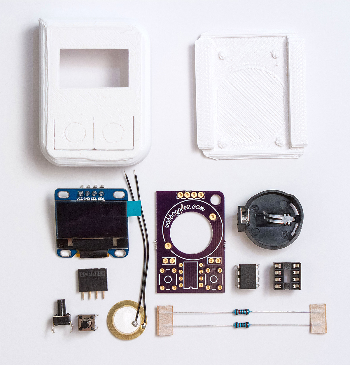
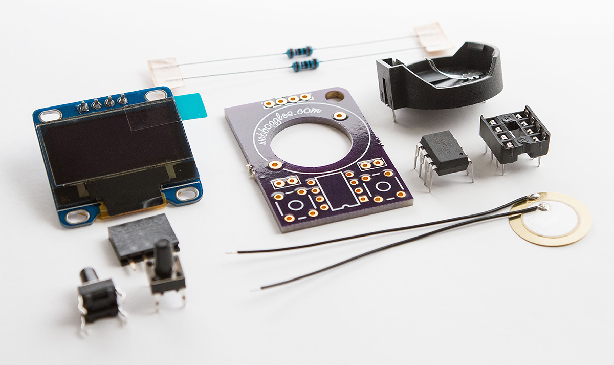
Photo of different parts if you are sourcing your own components with descriptions below.

| Title | Quantity | |
| 1. | 3D Printed Snap Case | 1 |
| 2. | Printed Circuit Board download printable pdf |
1 |
| 3. | SSD1306 OLED Screen | 1 |
| 4. | 4 pin 2.54 female header | 1 |
| 5. | CR2032 Battery | 1 |
| 6. | CR2032 Battery Holder | 1 |
| 7. | Pulldown resistor | 2 |
| 8. | Pushbutton | 2 |
| 9. | Attiny85 | 1 |
| 10. | DIP8 socket | 1 |
| 11. | Piezo speaker | 1 |
| 12. | 10uf capacitor (used with arduino when programming Attiny85) |
Schematic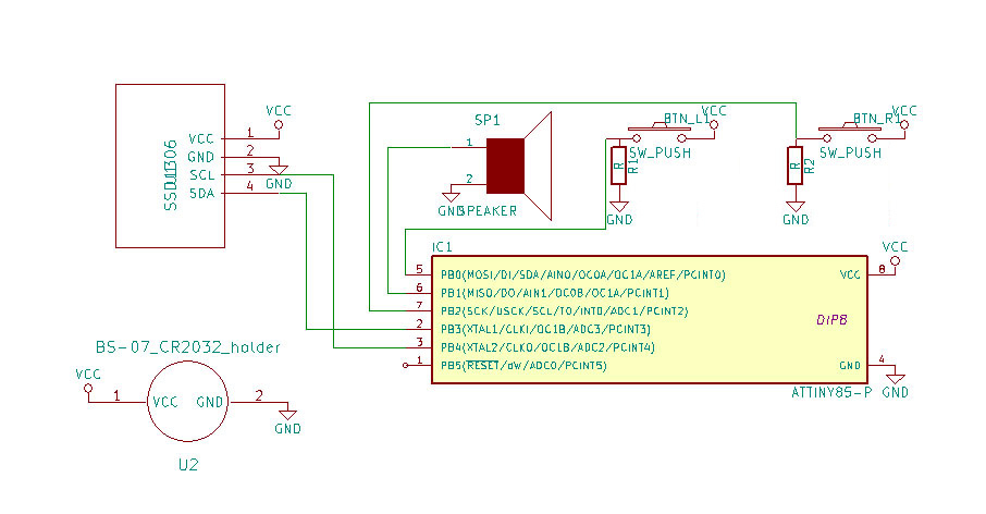
Please note that if you are sourcing the parts yourself, you will need to program the Attiny85 with the 8 mhz internal clock bootloader and then the game sketch before it will work.
You can download and print the case through 3D Hubs, Shapeways or Sculpteo.
A great guide on programming the Attiny85 with Arduino IDE can be found on the high-low tech group’s website: http://highlowtech.org/?p=1695
To flash the Attiny85 you will need the updated game code linked above
as well as the screen library from the tinusaur project: https://bitbucket.org/tinusaur/ssd1306xled (put the files into the Arduino Libraries Folder), unless of course you want to write your own game for the device in which case I would love to see what you create!
Some more photos
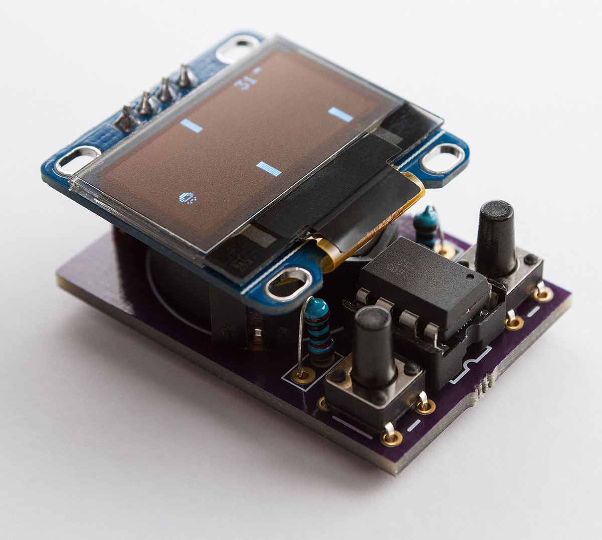
Note the case may need extra finishing (ie sanding, filing, a brush with acetone to gloss it up etc. be safe)

Hi Ilya,
I’m very interested in your project. Congratulations for the hard work you done here. I’m working in a fork of your project in GitHub, trying to refactor some code and inspiring my self to develop new games. All depends in my free time, which is very spare 🙁
https://github.com/pakozm/TinyGames
So, looking into your schematic, I think the pull-down resistors are not placed properly. May be they should be placed connecting the input pin to GND through the resistor when the button is inactive, however in the schema they are placed connecting VCC to GND through the resistor.
Thanks for pointing that out Paco, I was playing with KiCAD one day and made the schematic, obviously wasn’t concentrating. I’ve fixed the image.
I want to make snake next, I think it could be quite fun, but also don’t have much time at the moment…
Hi Ilya,
I really love the games you made. I would love to get them working on my attiny but always get the same error message.
‘ssd1306_init’ was not declared in this scope
I put this in my libraries https://bitbucket.org/tinusaur/ssd1306xled but still I got this error. Any idea?
Hi Andreas, many people seem to be having this issue. Here are my hardware and library folders I’m using with Arduino 1.0
https://drive.google.com/file/d/0B3bO_ZNaxxnlUGt5MnBjeEdnLU0/view?usp=sharing&resourcekey=0-w979b4pXWmMLka7_f0kU5w
Hello Andreas,
Iam trying to build this arcade project and I also get “ssd1306_init”was not declared in this scope. Have you managed to find a solution yet?
Please email me
[email protected]
I have made some posts on forums…
Can we call it TinyBoy?
CHIPMUSIC.ORG
http://chipmusic.org/forums/topic/18346/tinyboy/
UZEBOX.ORG
http://uzebox.org/forums/viewtopic.php?f=10&t=2359
Can it have up,down,left,right and one fire button?
Call it what you like, send me photos of what you make with it!
It’s going to be challenging to get the attiny working with more buttons, try analog read with different resistor values for each button.
ive attempted to make this but get nothing on the screen lol i used the ebay knock off oled here http://www.ebay.com/itm/221957276858?_trksid=p2060353.m2749.l2649&ssPageName=STRK%3AMEBIDX%3AIT
is there anything different i need to do?
Hi you probably figured it out but the screen you link to has vcc and gnd swapped around
The interwebs say it’s spelled Ouroboros.
I had the MCU and display laying around so I rebuilt this on a piece of proto board as soon as I saw it. I’ve lost many hours with UFO Escape already. Great stuff, thanks.
Glad you liked the game! Picked “oroboros” as shorter and less common name. According to wikipedia “A simplified English spelling of oroboros is encountered occasionally in the 20th century.” but who cares right? =)
Hi Ilya,
What a great project! Any chance you can share your OSH Park board on the OPSHPark website?
Thanks!
Thanks Brian, I am sorry but I will not be releasing the final board designs at this point. You can however make your own board using the printable PDF and the laser printer & iron transfer method.
Olá,
Your project is very good.
I’m having trouble, any chance of running on the SSD1306 128×64 OLED screen with the following pins?
Pines:
OLED_MOSI 9 // => SDA
OLED_CLK 10 // => SCK = SCL
OLED_DC 11 // => A0 = D / C
OLED_CS 12 // => does not use
OLED_RESET 13 // => Reset
H,
I’m having trouble, any chance of running on the SSD1306 128×64 OLED screen with the following pins?
Pines:
OLED_MOSI 9 // => SDA
OLED_CLK 10 // => SCK = SCL
OLED_DC 11 // => A0 = D / C
OLED_CS 12 // => does not use
OLED_RESET 13 // => Reset
Your project is very good.
Hi, not sure what you are trying to do but the 4 pin screen (VCC, GND, SCL, SDA) is I2C protocol however MOSI is an SPI protocol pin so I’m guessing no. What microchip and what screen module are you using?
how long is the battery life?
Generally pretty long, few days to months depending how much you play provided soldering flux is cleaned up.
Hi!
I need to connect the temperature sensor mlx90614 and the oled 128×32 i2c screen to the attiny85 processor. Could you pleeeeeease help me?
Hi, you should be able to use all the same code, I believe the frame will just get clipped with your smaller screen
I was getting garbage in my Oled i2d display but I finally succeeded grounding CS pin and connecting a 100nF cap and a 10K ohm resistor between VCC and RES pin. I built a prototype in a breadboard and connected a CR2032 button cell but the game consumes too much juice. I’ve read in the comments that it should last months but how in the world did you managed to do that? ATtiny85 consumes at least 3mA (@2.7V and 8 Mhz) and CR2032 cell is able to deliver 0.2mA continuously (cell is able to supply more current in pulse discharge mode, which is not our case). If we add the display plus the piezo buzzer, cell’s voltage drops fast to the point that the oled shuts down (though connecting a cap in parallel helps). I’m afraid I will have to connect two AA 1.5 batteries for this project (or better a 3.7V li-ion rechargeable battery). Did anyone had the same problem or can shine some light of what I’m doing wrong?
Hi Carlos, it sounds like you are using a different model screen, there is no CS pin on the screens used with this kit (surprised you got it working with an SPI screen)
The “months” was probably referring to sleep mode, you will probably get a couple of days of continuous operation.
Please share your schematic and photos of the bradboard.
Thanks ilya for your reply. I am using an OLED display that can be configured either as SPI or IIC…so I’ve configured it as IIC. These are the cheap OLED displays found in aliexpress…
https://www.aliexpress.com/snapshot/0.html?spm=a2g0s.9042647.6.2.Iq3AHj&orderId=86577238028092&productId=32798913743
schematic is the same as the one posted here. I’ll keep playing with it and let you know about my findings.
Hi ilya! I am trying to port the game to an Atmega328P and I’m failing to do so. This is what I tried so far:
Burned an internal 8 Mhz clock
SSD1306_SCL PC5 // Used to be PB4
SSD1306_SDA PC4//Used to be PB3
//PCMSK = 0b00000001; // pin change mask: listen to portb bit 1
PCMSK0 = 0b00000001; // pin change mask: listen to portb bit 1
// GIMSK |= 0b00100000; // enable PCINT interrupt
PCICR |= 0b00000001; // turn on port b
digitalRead (2) to digitalRead(10)
digitalRead (0) to digitalRead(8)
in void beep(int bCount,int bDelay)
changed digitalWrite(1,HIGH);
to
digitalWrite(9,HIGH);
It compiles just fine and seems that it is working, because I can listen the beeps in the buzzer, can wake up the uC by pressing the PB0 button but cannot see anything in the OLED. Any ideas of what I could be missing?
Hello Ilya,
i’m trying to make the breakout game. got all the libraries and compiled the ino. to the attiny after i first set the bootloader. no problem. now to breadboard everything as shown in drawing(check&double check). power on and NO display, also buttons don”t work(tried pull up and down).
I can get the display to work if I connect the button pins pb0/pb2 to the display, but it only shows the “breakout logo”,etc. . I tried swapping the button/function pins over to pb3/pb4 but nothing happens. “HELP”
has anyone actually made this?
please respond.
Hi ilya!
I have upgraded the ATtiny85 chip to one of the new ATtiny1614 chips. It has twice the Flash Memory and Static RAM. I managed to fit four games with a menu into a single console.
Full instructions at https://www.hackster.io/john-bradnam/attiny1614-arcade-91564a
That’s really good, well done!
Hello Ilya,
i’m trying to make the breakout game. got all the libraries and compiled the ino. to the attiny after i first set the bootloader. no problem. now to breadboard everything as shown in drawing(check&double check). power on and NO display, also buttons don”t work(tried pull up and down).
I can get the display to work if I connect the button pins pb0/pb2 to the display, but it only shows the “breakout logo” . I tried swapping the button/function pins over to pb3/pb4 but nothing happens. “HELP”
Hi Ilia,
I am trying to upload https://github.com/stratosb/Attiny-Arduino-Games/tree/master/Pacman_Attiny_Arcade on ATTiny85 with 16Mhz internal clock bootloader, but I get the following error. Can you please help? Thank you.
c:/program files (x86)/arduino/hardware/tools/avr/bin/../lib/gcc/avr/7.3.0/../../../../avr/bin/ld.exe: C:\Users\stratos\AppData\Local\Temp\arduino_build_327359/Pacman_Attiny_Arcade.ino.elf section `.data’ will not fit in region `text’
c:/program files (x86)/arduino/hardware/tools/avr/bin/../lib/gcc/avr/7.3.0/../../../../avr/bin/ld.exe: region `text’ overflowed by 152 bytes
collect2.exe: error: ld returned 1 exit status
exit status 1
Hi, it looks like your sketch is bigger than the flash size, there is a fix for it although I can’t remember now, you might need to use the newer version of Arduino for Andy’s game as I recall having trouble flashing them on my original setup.